Learn below how to wire relay boards, steppers, limit boards and the physical button pendent. We designed wiring the Ready Motion Controller to be as easy as possible and as minimal as we could. If you have any questions please call or shoot us a email here.
Download the manual here.
**MAKE SURE ALL POWER IS OFF BEFORE WIRING ANYTHING UP. IT WILL CAUSE DAMAGE**
**NEVER UNPLUG ANY DB CABLES WHILE POWER IS ON. IT WILL CAUSE DAMAGE**
- Mounting Boards
- Wiring Steppers/Servos
- Wiring Pendent
- Wiring Relay Boards
- Wiring Limit Boards
- Wiring External 24 Volts to Supply Rail
Mounting Boards:
Layout the Ready Motion Boards how you want and use the stand offs to mount them

Use a 6/32 tap to mount the stand offs to your sub panel

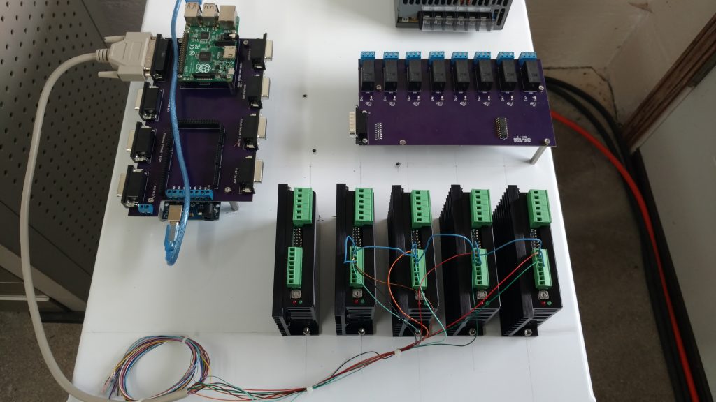
The Ready Motion Board Mounted

Wiring Relay Boards:
Next hook up the DB-15 cables from the Main Board to the Relay Boards


Wiring Steppers:
Now lets hook DC power to the drives run 24 – 65 VDC power to the V+ V- terminals. We use jumper wire to go from drive to drive.
Now we will hook up the 4 stepper motor leads up
NOTE: If you want to change stepper direction swap the A+ and A- wires
Stepper Motor A+, A-, B+, B- Color Codes:
-
A + : WHITE
-
A – : RED
-
B + : GREEN
-
B – : BLACK
Now we will hook up the Stepper drives with the DB-25 Cable
(Below the pictures is the wire color chart for wiring)
First We will wire the DB-25 cables GRAY wire to the (STEP – and DIRECTION -).We use jumper wire to go from drive to drive.
Time to hook up (STEP + and DIRECTION +)
Stepper Color Codes:
-
X Axis:
- STEP = BLACK / WHITE
- DIRECTION = RED / WHITE
-
Y Axis:
- STEP = GREEN
- DIRECTION = BLUE
-
Z Axis:
- STEP = BROWN
- DIRECTION = RED / BLACK
-
A Axis:
- STEP = GREEN / WHITE
- DIRECTION = BLUE / WHITE
-
B Axis:
- STEP = BROWN / WHITE
- DIRECTION = ORANGE
-
C Axis:
- STEP = GREEN / BLACK
- DIRECTION = PURPLE
-
D Axis:
- STEP = RED
- DIRECTION = ORANGE / WHITE
-
E Axis:
- STEP = LIGHT GREEN
- DIRECTION = PURPLE / WHITE
-
GND:
- GRAY (IF using Ready Motion 6.5 AMP Drives wire the GND to STEP – and DIRECTION -)
-
5 VOLT:
- YELLOW/BLACK (IF using Ready Motion 6.5 AMP Drives don’t use this at all


Connect the DB-25 Cable to the Ready Motion Board
Wiring Limit Board:
Lets start with just hooking up the DB cable to the limit board 
OK next run 24 volt + supply from the power supply or extra 24 volt rail terminals to the + terminals on the limit board. We use jumper wire to go from + terminal to + terminal
Next run 24 volt – supply from the power supply or extra 24 volt rail terminals to a leg on your limit switch. Then hook the other leg of you limit switch to the – terminal on the axis you want to use on the limit board.
NOTE: If you are not using the Ready Motion Control main board you can still use our limit board by hooking your motion controllers limit inputs to the break out terminals located below. The terminals are in order from left to right X,Y,Z
Wiring 24 Volt Rail:
Hook 24 volt VDC to the + and – Terminals on the 24 volt rail.
NOTE: Only hook one supply to the + and – on the rail. The other terminals are to supply back out if needed.
Finally add the sub panel to your electrical enclosure


